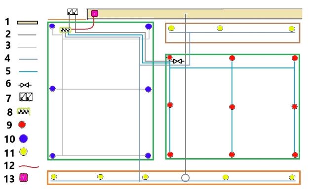
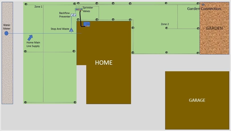
Sprinkler Zone Layout and Laterals
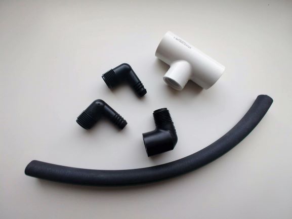
- 3/4" PVC pipe Schedule 40
- 3/4" Slip PVC Tee
- 3/4" Slip x 1/2" Thread PVC Elbow
- Barbed swing pipe Fitting for Swing Joint Attachment
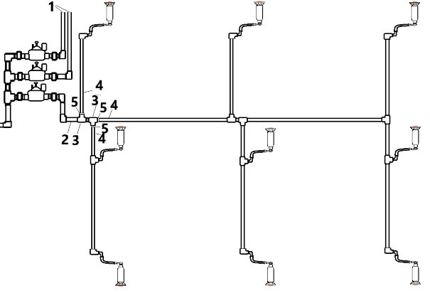
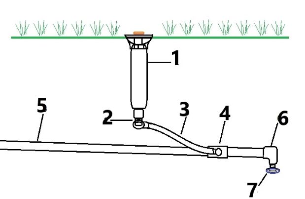
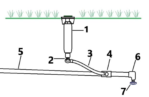
Sprinkler Zone Layout Example
- Laterals for Separate Zones
- 1" PVC Pipe Schedule 40
- 1" Slip Tee
- 3/4" PVC Pipe Schedule 40
- 1" x 3/4" Slip Reducer Bushing
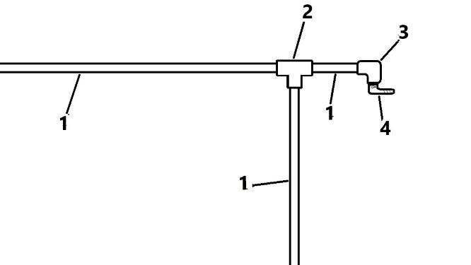
Sprinkler Zone Layout Explained
In this sprinkler zone layout example the pipe size remains 1 inch until the second Tee. After this Tee, the piping and fittings remain 3/4 inch up to the Funny Pipe connections. It is a good practice for the pipe size to remain 1 inch (if the available water is 9-16 GPM) until the first Tee, or until the zone has supplied 1/3 of the sprinkler heads. In this example we will assume that the sprinkler heads are 1804's with Rain Bird 15 nozzles. In that case this zone would be using 13.86 GPM, this rate of flow is too high for a 3/4" line to supply. Your objective is not to exceed 5 feet per second. It would be ideal to calculate the flow at each point in a system, but that is not realistic in most cases. Instead, I reduce the pipe size after I have installed 1 Tee that diverts the water relatively equally, or after I have installed the fittings that supply 1/3 of the sprinkler heads.
1/2" PVC
You may have noticed that I have not included 1/2" PVC. I never install 1/2" PVC, I run 3/4" to the last PVC fitting and at that point I use Funny Pipe. I find that this method saves a ton of time and has no adverse effects on the performance.