Sprinkler System Installation Examples: A Comprehensive Guide

Sprinkler system layout example plans

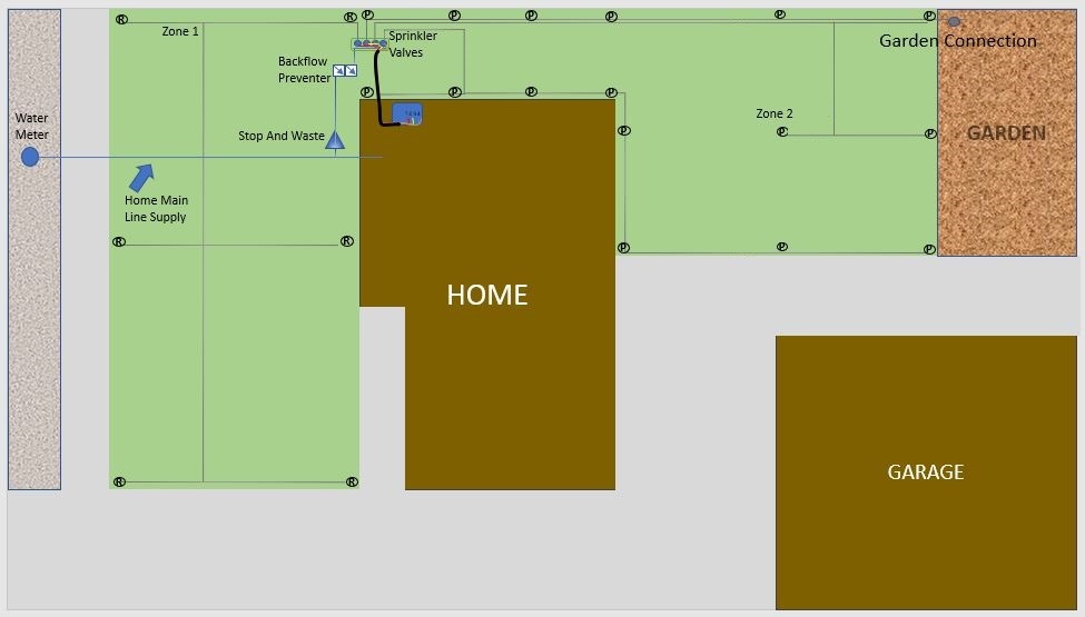
System Layout Example

  1. Residence
  2. Main Line
  3. Zone 1
  4. Zone 2
  5. Zone 3
  6. Stop and Waste
  7. Backflow Preventer
  8. Automatic Sprinkler Valves
  9. Pop-up Spray Sprinkler Head
  10. Rotor Sprinkler Head
  11. Drip Connection or Bubbler
  12. Wiring for Irrigation Valves
  13. Irrigation/Sprinkler Timer

This is an example of what the layout of a front yard sprinkler system may be like. The laterals are color-coded to avoid confusion.

Sprinkler Head Layout

Sprinkler head layout is perhaps the most important part of your personal installation. If you don't have a proper layout, you won't have good performance and will likely waste thousands of gallons of water each season.

Head to Head Coverage

Head to head coverage means every spot in the irrigated area needs to be covered by at least 2 sprinkler heads, and each head should throw water far enough to reach or slightly overlap the adjacent heads. This is done by considering each sprinkler as a geometric shape based on its ARC and Radius ratings.

Sprinkler Coverage Layout Example

Layout Examples

The shapes in the pictures represent the space between sprinkler heads.

Sprinkler Coverage square pattern Layout Example

Square Pattern Layout

Each sprinkler head used in these examples are full heads to help demonstrate how important layout can be.

Sprinkler coverage triangle pattern Layout Example

Triangle Pattern Layout

The triangle pattern (actually called a diamond pattern) is more efficient but less common because it's more difficult to lay out. Most residential sprinkler systems use the square pattern.

Layout Process

Layout can be simple. Walk around the property with a measuring tape or wheel, placing flags according to available products based on distance. Start with corners, measure sides, and determine appropriate sprinkler head types and sizes. Transfer the layout to paper or computer for review.

Measuring the property for spacing of Sprinklers

Measuring for Layout

Measure the property for spacing of Sprinklers

Layout plans using sprinkler heads

Creating the Layout

Create a layout using sprinkler heads; use rotors for larger areas if possible.

Sprinkler system layout plan example

Complete System Layout

This is an example of an actual sprinkler system layout.

Sprinkler system layout and coverage example

Coverage Analysis

As you can see, the layout is good, but there are still gaps in overlapping coverage. This is a common and unavoidable problem.

Stop and Waste Example schematic

Stop and Waste Valve

A stop and waste valve is essential in areas with hard freezes. It's a shutoff valve that drains downstream water from the main line, typically installed near the properties water connection/meter.

Backflow Preventers

A backflow preventer is required for any sprinkler system supplied from culinary water (drinking water). It prevents the undesirable reversal of flow into the potable water supply.

Why Do I Need A Backflow Protection Device?

A Backflow Preventer protects drinking water from becoming contaminated in the event of a loss in pressure from the supply, the backflow preventer prevents the water from flowing backwards.

Backflow Preventer PVB schematic, Pressure Vacuum Breaker

PVB (Pressure Vacuum Breaker)

The PVB is a popular choice for its ease of installation and cost-effectiveness. It's suitable for most sprinkler systems but doesn't protect against back pressure.

Backflow Preventer RP schematic, Reduced Preventer Assembly

RP (Reduced Pressure Assembly)

The RP offers the best protection for sprinkler systems connected to pressurized culinary water systems. It's more expensive but provides comprehensive protection.

Measuring Water Supply for GPM

Measuring Water Supply

To measure your water supply, use a 5-gallon bucket and time how long it takes to fill from a fully open hose bib.

Measure GPM Tool

GPM Measurement Notes

Keep in mind that measurements from the house may not be accurate. For best results, measure after installing the stop and waste valve. Your target rate should be close to the maximum GPM for your property main line.

Trenching, Digging or excavating, trench that has been dug with a machine

Trenching and Digging

Warning! Always have utilities located before digging. In the U.S., call 811 or visit Blue Stakes for this free service.

Trench Depth

For systems designed to drain when not under pressure, pipes don't need to be very deep. A good rule is to measure the body of your most commonly used sprinkler heads, then add 2 inches. For residential properties

Trench Depth (Continued)

For residential properties, never go deeper than 12 inches to avoid problems with utilities. After connecting to the stop and waste, bring the irrigation supply main line up to this depth before running the remaining irrigation main line for the system.

Teflon tape

Teflon and Pipe Dope

Use these sealants on threaded fittings.

Sprinkler Valves Manifold Assembly Example

Manifold

This setup has 3 valves (one drip valve kit and 2 DVF valves), a gate valve to shut this valve bank down for minor repairs, and a ball valve used as a winter drain.

Sprinkler Valve Manifold schematic

Manifold Schematic

All Fittings are PVC:

  1. 1 Inch Tee Slip x Thread
  2. 1 Inch Close Nipple
  3. 1 Inch Union Threaded
  4. 1 Inch Close Nipple
  5. 1 Inch Valve DVF
  6. 1 Inch Toe Nipple
  7. 1 Inch Union Slip
  8. Optional Drip Filter
  9. Optional Hose Bib/Ball Valve (Used for Winterization)

Manifold Assembly Tips

Preferred setups are 2-4 DVF valves. When assembling threaded components, wrap the threads 3 times with Teflon tape and for extra insurance apply a small amount of thread sealant to the fittings on the main line side of the valves. Do not over-tighten; if using both Teflon tape and thread sealant, hand-tight should be sufficient.

Sprinkler Valve Wiring Example

Valve Wiring

Use approved wire designed for sprinkler systems. Choose a color (typically white) for the common wire, which connects to each valve. Then, connect a different color wire to each valve for individual control.

Sprinkler Zone Layout schematic

Sprinkler Zone Layout and Laterals

  1. 3/4" PVC pipe Schedule 40
  2. 3/4" Slip PVC Tee
  3. 3/4" Slip x 1/2" Thread PVC Elbow
  4. Barbed swing pipe Fitting for Swing Joint Attachment
Sprinkler Zone Layout Example schematic

Zone Layout Example

  1. Laterals for Separate Zones
  2. 1" PVC Pipe Schedule 40
  3. 1" Slip Tee
  4. 3/4" PVC Pipe Schedule 40
  5. 1" x 3/4" Slip Reducer Bushing

Zone Layout Explained

In this example, the pipe size remains 1 inch until the second Tee. After this, piping and fittings remain 3/4 inch up to the Funny Pipe connections. It's good practice for the pipe size to remain 1 inch (for 9-16 GPM) until the first Tee, or until the zone has supplied 1/3 of the sprinkler heads.

Sprinkler Swing Joint PVC parts

Swing Joints and Sprinkler Heads

Swing joints offer a flexible way to install sprinkler heads. The swing pipe length can vary, but for heads exceeding 3 GPM, keep the swing joint no longer than 18 inches.

Pop-up Swing Joint schematic

Pop-up with Swing Joint

  1. Pop-up Sprinkler Head
  2. 1/2" Marlex coupled with 1/2" Funny Elbow
  3. Funny Pipe
  4. 3/4" Slip x 1/2" Thread PVC Tee coupled with 1/2" Funny Elbow
  5. 3/4" PVC pipe Schedule 40
  6. Optional 3/4" Slip x 1/2" Thread PVC Elbow
  7. Optional 1/2" Auto Drain (Generally only 1 installed at the lowest point of each zone)
Rotor Swing Joint schematic

Rotor with Swing Joint

  1. Rotor Sprinkler Head
  2. 3/4" Marlex coupled with 3/4" Funny Elbow
  3. Funny Pipe
  4. 3/4" Slip x 1/2" Thread PVC Tee coupled with 3/4" Funny Elbow
  5. 3/4" PVC pipe Schedule 40
  6. Optional 3/4" Slip x 1/2" Thread PVC Elbow
  7. Optional 1/2" Auto Drain (Generally only 1 installed at the lowest point of each zone)