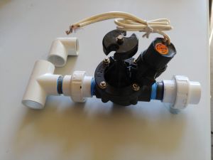
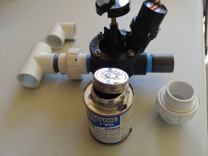
Single valve assembly example.
-
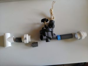
Parts you will need for each valve.
- 1 tee or elbow slip by thread 1"
- 2 close nipples 1"
- 1 threaded union 1"
- 1 automatic sprinkler valve 1"
- 1 slip union 1"
- 1 toe nipple (a nipple that is only threaded on one side, so it can be glued)
- Teflon
If you are using drip valves and filters, these are the parts you will need.
-
Parts you will need for each drip valve.
- 1 tee or elbow slip by thread 1"
- 2 close nipples 1"
- 2 threaded union 1"
- 1 automatic sprinkler drip valve 1", with drip basket filter.
- Teflon
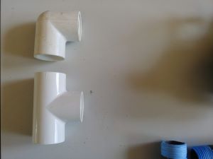
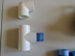
These fittings are for connecting to the main line (they are slip by thread fittings, so the valve can be threaded in, and the other fittings can be glued). If this is a replacement, you may not need these fittings as they may already be installed. If this is an upgrade then you will need to have a Tee or Elbow for each valve to be connected to the main line.
This is a close 1" nipple, while you can use any length of nipple for this fitting, it is nice to keep the manifold compact for accessibility. Make sure to use Teflon tape or pipe dope on all the fittings for the manifold.
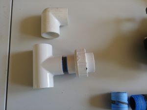
Next, thread on the first union. Being that this is only 1" pipe you only need to tighten the fittings to just over hand tight. If you are unsure how tight to thread these fittings, simply tighten to hand tight and check for leaks when you pressurize the main line. Over tightening will cause trouble in the future.
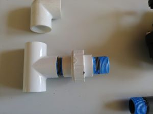
Next, Thread in another close nipple.
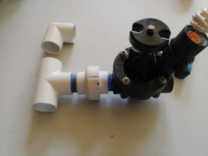
Thread on the valve. Make sure the valve is facing the right direction, all automatic valves are directional. There will be an arrow on the body to indicate the correct direction for installation. If for some reason you are unable to find an arrow, the solenoid will be on the lateral/non-pressure side.
Thread in a toe nipple and cut it to size. This nipple can be of any length, but I always cut it to keep the manifold compact for accessibility.
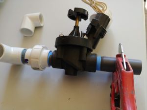
Glue on the slip union.
Congratulations, you have assembled your first valve. Assemble additional valves by repeating the steps.
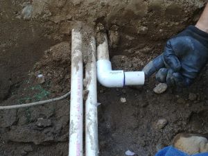
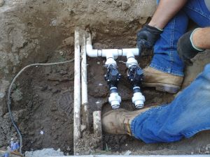
Prepare the main line for the first valve to be installed. This picture is of an upgrade where an old system was getting the valves moved to another location.
Glue on the first valve assembly. Follow proper gluing procedure. For more gluing information read the section on gluing basics.
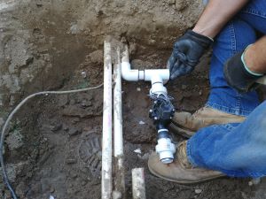
You will need to cut a short piece of pipe to glue between the next valve/s.
Add additional valves in the same manner.
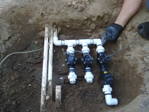
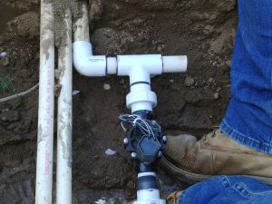
The last valve in the manifold may need to be an elbow instead of a tee. You can add as many valves as needed in the same fashion. Keep in mind that you will likely be able to fit only 4 valves inside each sprinkler box.
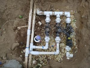
Finally, you will need to glue in the lateral connections to each corresponding valve.
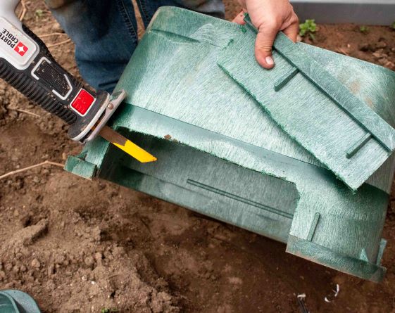
You may have to cut your valve box in order to set it level with the landscaping.
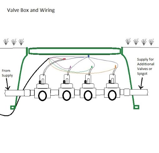
Lastly, you will need to wire the valves and backfill the box.
Valve wiring can be simple, but it can also cause problems if not done properly. When wiring valves, use an approved wire designed for sprinkler systems. If you take a closer look at the wire, each strand is color coded to make installation easier. When wiring valves, you need to choose a color to use as your common. The common wire is generally the white wire, but I have depicted it as Blue in the wiring image, just to make it stand out. As you can see, the common connects to each valve, along with a different color of wire run to each separate valve. When I wire valves, I always start by selecting one wire from each valve and connecting them to the common. Once you have the common connected, you will have one wire left for each valve. Simply connect a different color wire to each valve. The color doesn't matter, but I always stick to a color code to make it easier when installing the clock / sprinkler timer.
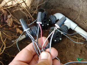
In this example, the installer had used the black as the common wire.
This is an example of the color code I use. I try to stick to a color code when I am installing. This helps to speed up the process when wiring the timer, especially when the customer wants their system to operate in a particular order. The color of wire you are using may be different.
Common Wire-White
- Red
- Yellow
- Blue
- Green
- Orange
- Purple
- Gray
- Black
- Pink